Introduction
We have already studied a lot about transformers in Bright Hub and we know that it’s simply a device used for either stepping-up or stepping down an applied input AC through magnetic induction in between its two windings.Basically a transformer will have the following main components:- Iron core stampings (configured either as U/T or E/I, generally the later is used more extensively)
- Central plastic or ceramic bobbin surrounded by the above iron core stampings
- Two windings (electrically isolated and magnetically coupled) using super enameled copper wire made over the bobbin
- Normally the winding which is designated to receive the input supply is termed as the “Primary” and the winding which in response to this input produces the required induced voltage as the output is termed as the “secondary” winding.
Designing your own transformer as per a specific application can be interesting, but not feasible without calculating the various parameters typically involved with them. The following discussion will take you through a few important steps and formulas and explain how to make a transformer.Calculating the Core Area (CA) of the Transformer
The Core Area is calculated through the formula given below:- CA = 1.152 ×√ (Output Voltage × Output Current)
- Calculating Turns per Volt (TPV)It is done with the following formula:TPV = 1 / (4.44 × 10⁻⁴ × CA × Flux Density × AC frequency)where the frequency will depend on the particular country’s specifications (either 60 or 50 Hz), the standard value for the flux density of normal steel stampings may be taken as 1 Weber/sq.m, for ordinary steel material the value is 1.3 Weber/sq.m
Primary Winding Calculations
Basically three important parameters needs to be figured out while calculating the primary winding of a transformer, they are as follows:- Current through the primary winding
- Number of turns of the primary winding
- Area of the primary winding
Let’s trace out each of the above expressions:Primary Winding Current = (Secondary Volts × Secondary Current) ÷ (Primary Volts × Efficiency), the average value for the efficiency of any transformer nay be presumed to be 0.9 as a standard figure.Number of Turns = TPV × Primary VoltsPrimary Winding Area = Number of Turns / Turns per Sq. cm (from the table A)Reading Table A is easy – just find out the relevant figures (wire SWG and Turns per sq.cm.) by tallying them with the closest matching value of your selected primary current.Secondary Winding Calculations
As explained above, with the help of Table A you should be able to find the SWG of the wire to be used for the secondary winding and the TPV simply by matching them with the selected secondary current.The Number of turns for the secondary winding is also calculated as explained for the primary winding, however considering high loading conditions of this winding, 4 % extra turns is preferably added to the over all number of turns. Therefore the formula becomes:Secondary Number of Turns = 1.04 × (TPV × secondary voltage),Also secondary winding area = Secondary Turns / Turns per sq. cm. (from table A).Calculating the Core Size of the Steel Laminations or the Stampings
The core size of the steel stampings to be used may be easily found from Table B by suitably matching the relevant information with Total Winding Area of the transformer. The Total Winding Area thus needs to be calculated first, it’s as follows:Total Winding Area = (Primary Winding Area + Total Secondary Winding Area) × Space for External Insulation.The third parameter i.e. the space for the insulation/former etc. may be taken approximately 25 to 35 % of the sum of the first two parameters.Therefore, the above formula becomes:Total Winding Area = (Primary Winding Area + Total Secondary Winding Area) × 1.3
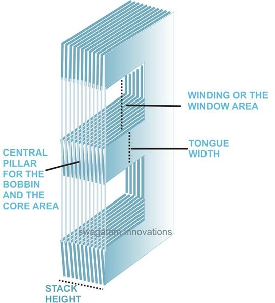
Normally, a core having a square central pillar is preferred and used - other factors involved are also appropriately illustrated in the adjoining figure and calculated as follows:Gross Core Area = Core Area from Table B / 0.9 (sq.cm.)Tongue Width = √Gross Core Area (cm)After calculating the Tongue Width, it may be used as a reference value and matched appropriately in Table B to acquire the actual CORE TYPE.Your quest regarding how to make a transformer gets over when you finally finish calculating the stack height, using the formula:Stack Height = Gross Core Area / Tongue Width.Table A
The table below helps you to select the gauge and turns per sq. cm of copper wire by matching them with the selected current rating of the winding appropriately.SWG------- (AMP)------- Turns per Sq.cm.10----------- 16.6---------- 8.711----------- 13.638------- 10.412----------- 10.961------- 12.813----------- 8.579--------- 16.114----------- 6.487--------- 21.515----------- 5.254--------- 26.816----------- 4.151--------- 35.217----------- 3.178--------- 45.418----------- 2.335--------- 60.819----------- 1.622--------- 87.420----------- 1.313--------- 10621----------- 1.0377-------- 13722----------- 0.7945-------- 17623----------- 0.5838--------- 4224----------- 0.4906--------- 28625----------- 0.4054--------- 34126----------- 0.3284--------- 41527----------- 0.2726--------- 50428----------- 0.2219--------- 60929----------- 0.1874--------- 71130----------- 0.1558--------- 88131----------- 0.1364--------- 99732----------- 0.1182--------- 113733----------- 0.1013--------- 130834----------- 0.0858--------- 160835----------- 0.0715--------- 190236----------- 0.0586---------- 228637----------- 0.0469---------- 280038----------- 0.0365---------- 350739----------- 0.0274---------- 483840----------- 0.0233---------- 559541----------- 0.0197---------- 654342----------- 0.0162---------- 775543----------- 0.0131---------- 933744----------- 0.0104--------- 1145745----------- 0.0079--------- 1439246----------- 0.0059--------- 2022347----------- 0.0041--------- 2754648----------- 0.0026--------- 3970649----------- 0.0015--------- 6213450----------- 0.0010--------- 81242Table B
This Table B enables you to make your own transformer design by comparing the calculated Winding Area with the relevant required Tongue Width and Lamination Type number.Type-------------------Tongue----------WindingNo.---------------------Width-------------Area17(E/I)--------------------1.270------------1.21312A(E/12I)---------------1.588-----------1.89774(E/I)--------------------1.748-----------2.28423(E/I)--------------------1.905-----------2.72330(E/I)--------------------2.000-----------3.00021(E/I)--------------------1.588-----------3.32931(E/I)--------------------2.223-----------3.70310(E/I)--------------------1.588-----------4.43915(E/I)-------------------2.540-----------4.83933(E/I)--------------------2.800----------5.8801(E/I)----------------------2.461----------6.55514(E/I)--------------------2.540----------6.55511(E/I)---------------------1.905---------7.25934(U/T)--------------------1/588---------7.2593(E/I)-----------------------3.175---------7.5629(U/T)----------------------2.223----------7.8659A(U/T)----------------------2.223----------7.86511A(E/I)-----------------------1.905-----------9.0724A(E/I)-----------------------3.335-----------10.2842(E/I)-----------------------1.905-----------10.89116(E/I)---------------------3.810-----------10.8915(E/I)----------------------3.810-----------12.7044AX(U/T) ----------------2.383-----------13.03913(E/I)--------------------3.175-----------14.11775(U/T)-------------------2.540-----------15.3244(E/I)----------------------2.540----------15.8657(E/I)----------------------5.080-----------18.9696(E/I)----------------------3.810----------19.35635A(U/T)-----------------3.810----------39.3168(E/I)---------------------5.080----------49.803
Sunday, 7 September 2014
Designing Your Own Transformer
Subscribe to:
Post Comments (Atom)
No comments:
Post a Comment